The workflow editor
The workflow editor is the part of Porcupine you’ll probably spend most of your time building your pipeline. In this window, you’ll initialize the nodes of your pipeline and draw connections between them.
Nodes in Porcupine
When you open Porcupine, you’ll start with an empty workflow editor. To begin building your pipeline, you’ll have to initialize some nodes. A “node” represents a specific operation within your pipeline, ranging from neuroscience-specific operations like skullstripping or motion-correction to more generic operations like file I/O.
Currently, Porcupine provides nodes based on interfaces from two frameworks: Nipype, a Python-based software package providing wrappers for all major neuroimaging software packages, and TvM, a MATLAB-based laminar analysis package developed by Porcupine’s lead developer.
In this documentation, we’ll focus on explaining how to build Nipype-based pipelines in Porcupine.
Initializing nodes
To start building pipelines, you’ll of course need some nodes!
To initialize nodes, click the “Nodes” option in the left-upper corner of
Porcupine’s GUI. This should yield three options: Load Dictionary
(more on this later in the documentation),
TvM, and Nipype.
Hovering your cursor above the Nipype option then shows you all the Nipype-interfaces
that Porcupine supports. Selecting, for example, fsl and, in turn, preprocess
shows you all the available nodes from FSL’s preprocessing suite (including
BET and FAST from the image above).
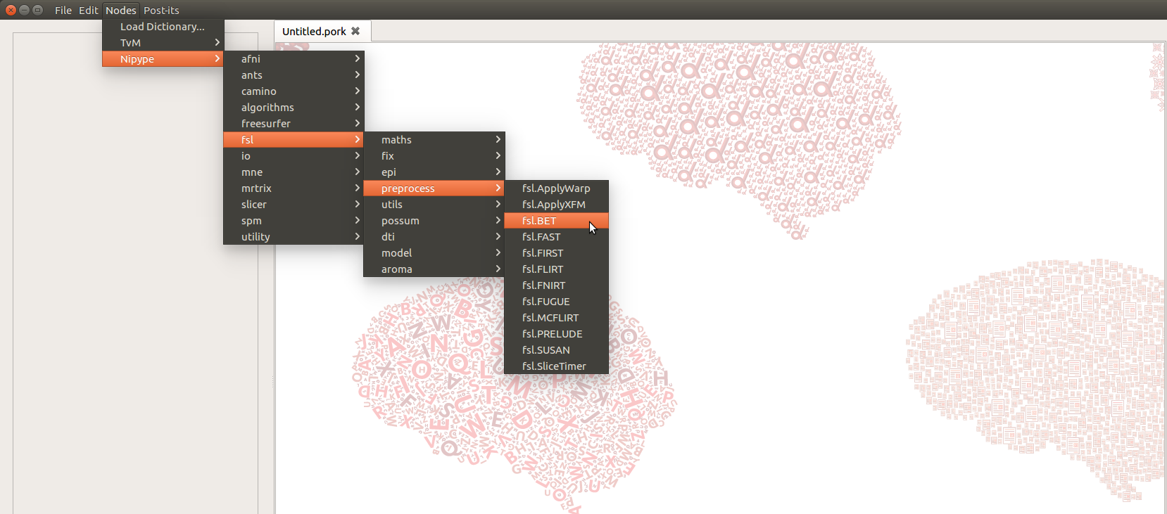
Clicking on one of these nodes (e.g. fsl.BET), then, creates a node in the
workflow editor!
Input-ports and output-ports
Now, suppose you’ve created an fsl.BET and an fsl.FAST node as in the above
example. Looking at, for example, the fsl.BET node, you see the name of the
interface (here “fsl.BET”) at the top of the node. Note that you can simply change
this default name, for example if you want to give it a more intuitive name
(like “skullstrip” instead of “fsl.BET”), by clicking on it.
Below the name of the interface, the node’s “ports” (as we call them) are listed.
Each port is either an input-port, recognizable by the little red dot on the
left side of the node, or an output-port, recognizable by the little red dot
on the right side of the node. In the screenshot of the FSL BET node below,
for example, the in_file parameter represents an input-port, while the
out_file, mask_file, outline_file, etc., represent the node’s output-ports.
(For Nipype-nodes, these input-ports correspond to the inputs attribute/traits
of nodes, and the output-ports correspond to the outputs attribute/traits.)
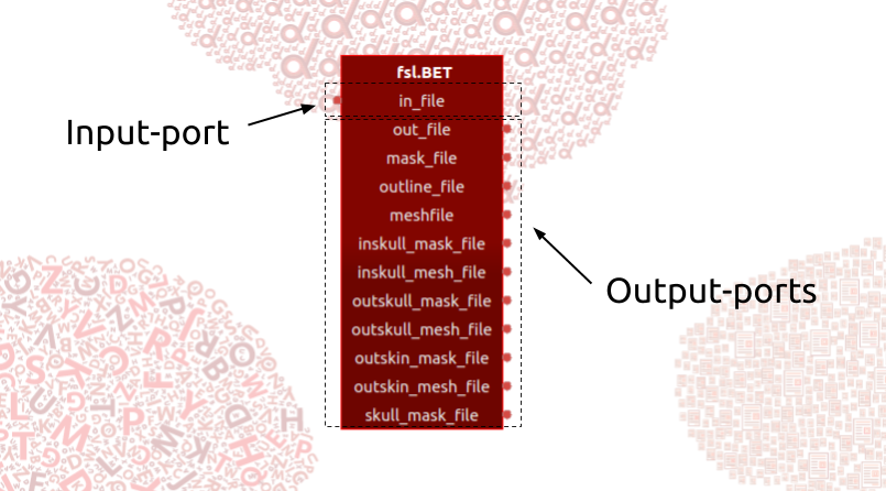
Importantly, by default, the node only shows the mandatory input-ports, while it shows by default all output-ports. In the next section on the node editor, you’ll learn how to access the node’s non-mandatory input-ports and how to control which output ports are shown and which are not (for example, to reduce the visual clutter in pipelines with nodes which have a lot of output-ports.).
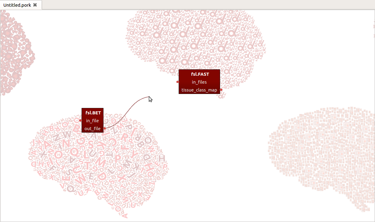
Connecting nodes
Given that you’ve initialized a couple of nodes, it’s trivially easy to connect
them. Just click on an output-port and drag your cursor towards another node’s
input-port, which draws a line between the two ports. In the example shown at
the start of this post, we could for example connect the out_file output-port
from the BET-node (representing the skullstripped structural file) with the
in_files input-port from FAST-node (representing the file(s) to be segmented).
Now, there’s more to building pipelines than initializing and connecting nodes. In the next section on the node editor, you’ll learn how to control the functionality and visualization of your ports in more detail.